Oak Development Technologies
  • IcyBlue
  • Oak Blog
  • Prototyping
  • Livestream
  • Open Source Projects
  • Contact
Tutorials, Announcements, and More from...

Oak Development 
​Technologies

Connect with us on Facebook, Twitter & Instagram!

(Tutorial) Expanding Qt Py Outputs With 74HC595

10/7/2020

1 Comment

 
Picture
The Adafruit Qt Py is an adorable development board with a lot of potential given the current price ($6 as of writing this). You might wonder with the small size, what if I need more outputs? In this tutorial we'll show you how you can expand the Qt Py's outputs using the 74HC595 serial shift register to drive a 7 segment display including the CircuitPython code to make it all work. 

As always before we get started, if you have never used a CircuitPython board like the QT PY, be sure to check out Adafruit's learning site to quickly get started with your new board. --> Adafruit Learning Site: Getting Started With CircuitPython

What you'll need:

To get started, you'll need the following parts:
  1. CircuitPython compatible development board (QT PY as used in this tutorial)
  2. USB-C data cable
  3. 1x 74HC595 Serial Shift Register
  4. 1x 5161AS-1 7 Segment Display
  5. A 1Kohm Resistor
  6. A solderless breadboard
  7. At least 15 jumper wires
  8. Mu Editor (Get that HERE)

​Getting Everything Wired Up:

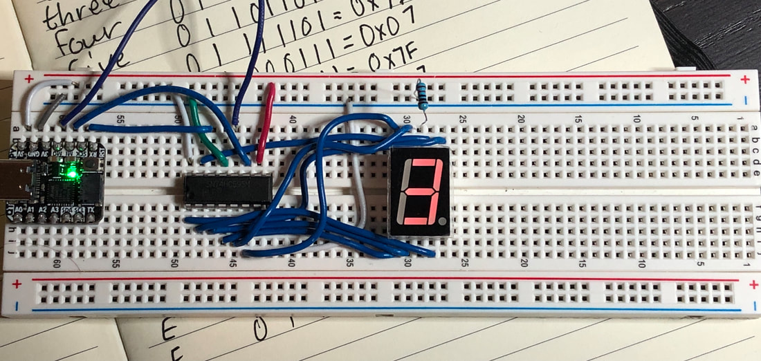
To get started, we first want to wire up our board. Connect your circuit just like the wiring diagram below. See the wiring steps if you need help.
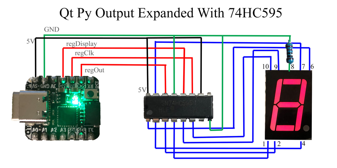
Picture
Wiring Steps:
  1. Connect the 5V pin on the Qt Py to the positive (+) rail of your breadboard.
  2. Connect the GND pin on the Qt Py to the negative (-) rail of your breadboard.
  3. Connect the VCC pin (pin 16) on the 74HC595 to the positive (+) rail of your breadboard.
  4. Connect the GND pin on the 74HC595 to the negative (-) rail of your breadboard.
  5. Connect the SCK/D8 pin on the Qt Py to pin 14 on the 74HC595.
  6. Connect the MI/D9 pin on the Qt Py to pin 11 on the 74HC595.
  7. Connect the MO/D10 pin on the Qt Py to pin 12 on the 74HC595.
  8. Connect pin 15 on the 74HC595 to pin 7 on the seven segment display.
  9. Connect pin 1 on the 74HC595 to pin 6 on the seven segment display.
  10. Connect pin 2 on the 74HC595 to pin 4 on the seven segment display.
  11. Connect pin 3 on the 74HC595 to pin 2 on the seven segment display.
  12. Connect pin 4 on the 74HC595 to pin 1 on the seven segment display.
  13. Connect pin 5 on the 74HC595 to pin 9 on the seven segment display.
  14. Connect pin 6 on the 74HC595 to pin 10 on the seven segment display.
  15. Connect the 1KOhm resistor to the negative (-) rail and pin 8 of the seven segment display.

​The Code: 

You'll want to make sure your CircuitPython board is ready to use with the CircuitPython .uf2 installed. If you need to, reference the Getting Started With Circuit Python link at the top of the article. 

First we are going to open the MU Editor. If your board is ready to use with Circuit Python, you should get no popups warning you about your board not being connected. For the sake of this post, we've included the code to display up to the number 5. You can easily expand this for 0 to 15 (F). In the editor window, we are going to paste the following code:

# Seven Segment + 74HC595 Shift Register Code

# import necessary libraries
from digitalio import DigitalInOut
from digitalio import Direction
import time
import board

# set up output pins to drive the 74HC595
regDisplay = DigitalInOut(board.D10)
regClk = DigitalInOut(board.D9)
regOut = DigitalInOut(board.D8)
regOut.direction = Direction.OUTPUT
regClk.direction = Direction.OUTPUT
regDisplay.direction = Direction.OUTPUT
# Reference table for making the numbers on the 7 segment display
# This determines how they are loaded.
# numer | 0 | g | f | e | d | c | b | a 
# zero  | 0 | 0 | 1 | 1 | 1 | 1 | 1 | 1 == 0x3F
# one   | 0 | 0 | 0 | 0 | 0 | 1 | 1 | 0 == 0x06
# two   | 0 | 1 | 0 | 1 | 1 | 0 | 1 | 1 == 0x5B
# three | 0 | 1 | 0 | 0 | 1 | 1 | 1 | 1 == 0x4F
# four  | 0 | 1 | 1 | 0 | 0 | 1 | 1 | 0 == 0x66
# five  | 0 | 1 | 1 | 0 | 1 | 1 | 0 | 1 == 0x6D
# six   | 0 | 1 | 1 | 1 | 1 | 1 | 0 | 1 == 0x7D
# seven | 0 | 0 | 0 | 0 | 0 | 1 | 1 | 1 == 0x07
# eight | 0 | 1 | 1 | 1 | 1 | 1 | 1 | 1 == 0x7F
# nine  | 0 | 1 | 1 | 0 | 0 | 1 | 1 | 1 == 0x67
# A     | 0 | 1 | 1 | 1 | 0 | 1 | 1 | 1 == 0x77
# B     | 0 | 1 | 1 | 1 | 1 | 1 | 0 | 0 == 0x7C
# C     | 0 | 0 | 1 | 1 | 1 | 0 | 0 | 1 == 0x39
# D     | 0 | 1 | 0 | 1 | 1 | 1 | 1 | 0 == 0x5E
# E     | 0 | 1 | 1 | 1 | 1 | 0 | 0 | 1 == 0x79
# F     | 0 | 1 | 1 | 1 | 0 | 0 | 0 | 1 == 0x71

# Make a lookup references for each hex number
zero = [0, 0, 1, 1, 1, 1, 1, 1]#0x3F
one = [0, 0, 0, 0, 0, 1, 1, 0]#0x06
two = [0, 1, 0, 1, 1, 0, 1, 1]#0x5B
three = [0, 1, 0, 0, 1, 1, 1, 1]#0x4F
four = [0, 1, 1, 0, 0, 1, 1, 0]#0x66
five = [0, 1, 1, 0, 1, 1, 0, 1]#0x6D
six = [0, 1, 1, 1, 1, 1, 0, 1]#0x7D
seven = [0, 0, 0, 0, 0, 1, 1, 1]#0x07
eight = [0, 1, 1, 1, 1, 1, 1, 1]#0x7F
nine = [0, 1, 1, 0, 0, 1, 1, 1]#0x67
A = [0, 1, 1, 1, 0, 1, 1, 1]#0x77
B = [0, 1, 1, 1, 1, 1, 0, 0]#0x7C
C = [0, 0, 1, 1, 1, 0, 0, 1]#0x39
D = [0, 1, 0, 1, 1, 1, 1, 0]#0x5E
E = [0, 1, 1, 1, 1, 0, 0, 1]#0x79
F = [0, 1, 1, 1, 0, 0, 0, 1]#0x71

# create a while loop to load the shift register
while True:
    # take user input on serial terminal of MU Editor
    number = int(input())
    # check the value of the number input
    if number == 0:
        # load the bits to be shifted into the shift register
        for i in zero:
            print("value of i %d",i)
            regOut.value = i
            # clock the serial clock pin of the shift register
            regClk.value = True
            time.sleep(0.01)
            regClk.value = False
    if number == 1:
        for i in one:
            print("value of i %d",i)
            regOut.value = i
            regClk.value = True
            time.sleep(0.01)
            regClk.value = False
    if number == 2:
        for i in two:
            print("value of i %d",i)
            regOut.value = i
            regClk.value = True
            time.sleep(0.01)
            regClk.value = False
    if number == 3:
        for i in three:
            print("value of i %d",i)
            regOut.value = i
            regClk.value = True
            time.sleep(0.01)
            regClk.value = False
    # Clock the display pin on the 74HC595
    regDisplay.value = True
    time.sleep(0.1)
    regDisplay.value = False


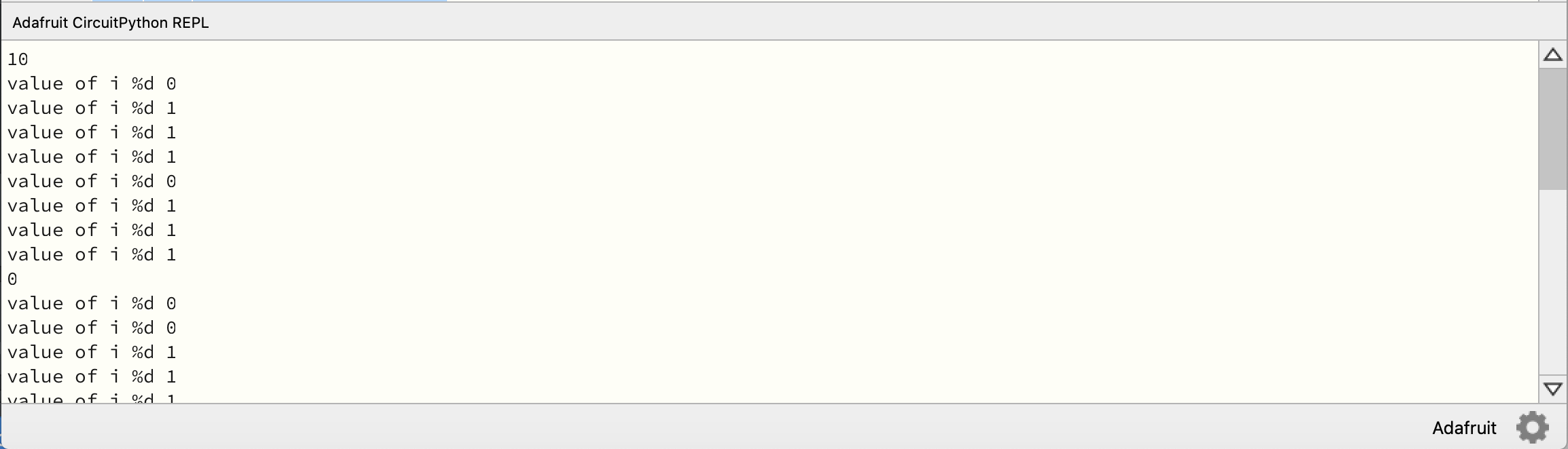
After you put this code in the MU Editor, Save the file as "code.py" and open the serial terminal in the editor. You should be able to enter a single numbers between 0 and 15 and hit enter. Once you hit enter, you should then see the serial prints of the bits being loaded and the seven segment display update on your breadboard.
Picture

Final Thoughts

This use of the shift register is just one of many for expanding outputs on smaller development boards. You can drive a large number of devices, and even hook multiple shift registers together to create even larger output pin options.

Thanks for working through this tutorial with us. Comment if you've done this tutorial or need help. As always, share on social media and let us know what tutorials you want to see!

​-Seth
1 Comment
GFE Colorado link
12/15/2022 11:02:50 am

Lovvely post

Reply


Leave a Reply.

    Authors

    Seth is embedded software engineer and open source hardware developer. 

    Archives

    May 2021
    April 2021
    January 2021
    November 2020
    October 2020
    September 2020

    Categories

    All
    New Products
    Product Spotlight
    Tutorials

    RSS Feed

Powered by Create your own unique website with customizable templates.
  • IcyBlue
  • Oak Blog
  • Prototyping
  • Livestream
  • Open Source Projects
  • Contact